Up front I'd like to say that this project was LONG and had it's share of ups and downs.
For this reason there are A LOT of pictures and the thumbs are smaller so this article wont be a kilometer long.
Like any project or task that runs in to trouble this was a great learning experience. When you sort out the problems you always learn something new.
This was the first time I opened up a C64 so research was needed time and again and some consulting of the Mssiah user forum and Big Mech's article on Prophet64 also the C64 archive is useful.
Some thanks are in order. This project wouldn't be possible without the contribution of "KickStart" (mad Commodore and especially Amiga enthusiast and collector) who provided me with a pair of C64c models needed. In return I built him a 1541EMU type 1 cable so there would be at least a little quid pro quo.
This project started when I came across D64 images for something called Prophet64. The predecessor for Mssiah that was available as a demo d64 set and a sold cartridge. Turning a Commodore 64 in to a musical instrument is just the kind off stuff I'm into: new, weird and interesting!
I did my initial research an decided to go for a 8580R5 SID based system with SID2SID modification to get 6 simultaneous voices/sounds and the 2 SID's in one C64 sounded kinky. To my delight both C64c's had 8580R5 SID's. Machine 1 was un opened but the case was beaten up and bleached by the sun. Machine 2 was opened, had some repair done and was missing 1 key but the case was in very good condition. Being suspicious and a little skeptical in nature I didn't want to use machine 2 as the base for my synth due to it's unknown repairs but rather go with the virgin machine 1. I did a little part swapping and ended up with a beautiful 80's icon in MINT condition and 2 8580R5 SID chips. So were ready to start assembly!
The SID2SID board costs only 4€ BUT I would gladly pay extra to get the right components with it. People have a hard time finding the long legged wiring (wrapping) socket needed to raise and connect the SID's to the motherboard AND getting the right transistor. Also as I discovered a factory preassembled SID2SID board would be a nice option. But enough wining for now and on to the soldering.


Assembly was easy. I used my "helping hand" to press the sockets down on the pcb but one could use tape etc.
The instructions say that the transistor should be soldered on the bottom side due to the leg order but you can always bend the legs and mount it on the right side and don't have to worry about short circuiting the graphics chip below. Note that the transistor will be replaced later to a more suitable one.

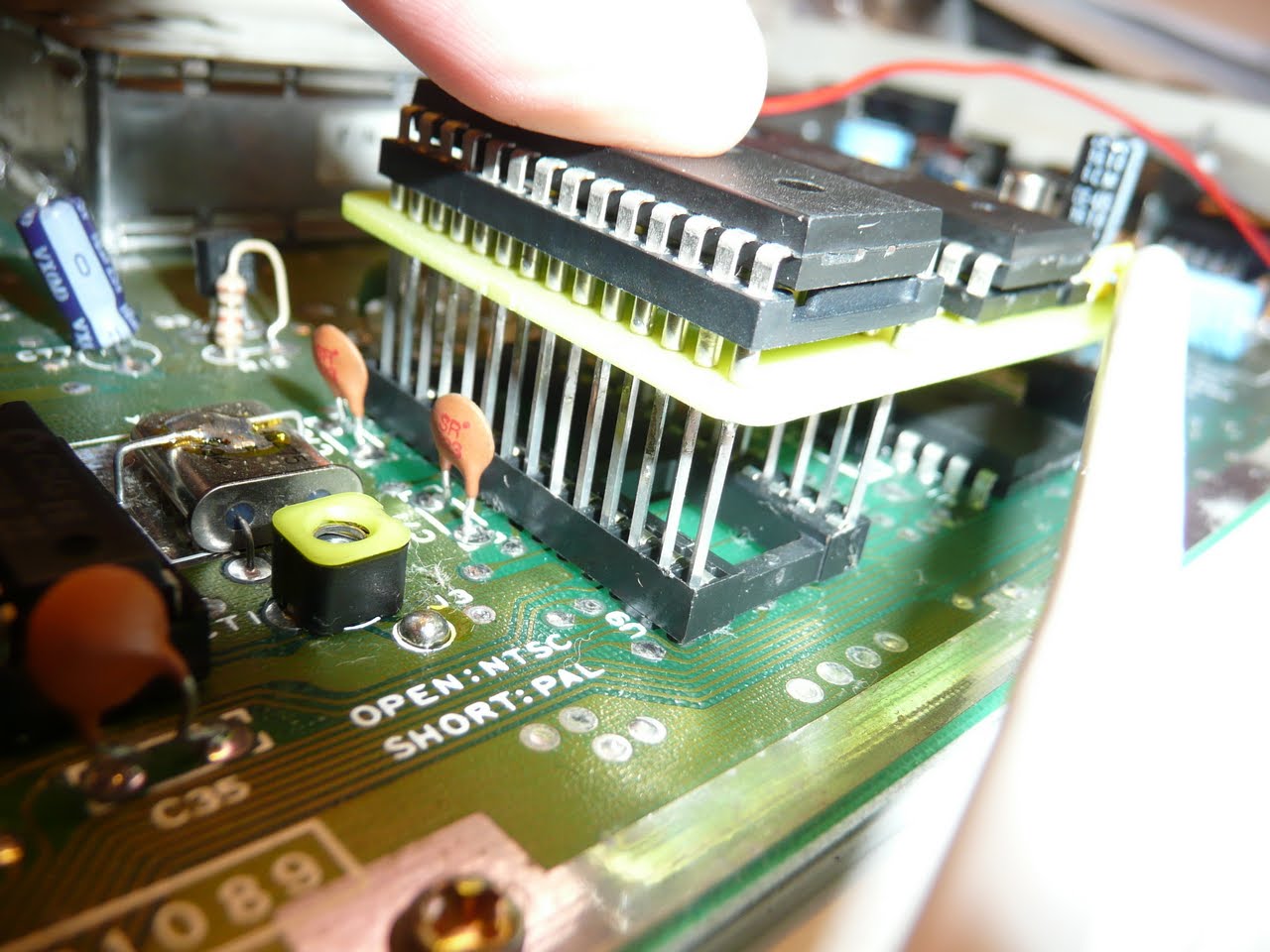


I test fitted the board but found the wrapping posts FAR too thick to fit in the socket and needed to be thinned. I cut a hole for the board in the metalized cardboard RF shield.

I filed the legs from both sides until they fit in the socket holes snugly. Then measured the hight and cut of the excess.


The SID2SID board fits nicely. I attached the robust audio (white) cable and the chip selection wire (red).
If you were lazy you could just make 1 audio out for the second SID and use the original DIN connector audio out for the original SID but that would be GAY!
Thats why I got me some Neutrik RCA connectors. After a little eye balling the innards of my C64 I came to the conclusion that the left side corner was the sturdiest and practical place to drill holes for the connectors. It's newer a good idea to save money on analog connections thats why I always try to use robust cable and Neutrik connectors.


All done and ready to go, or so I thought...
Plugged in the Mssiah cartridge and run the diagnostics to see if everything works. To my surprise there was no sound out of either SID!
The trouble shooter said that this can happen with 2 8580 SID's and a weak transformer. I tested both transformers I have. No difference. did a quick google but found nothing on a better transformer. The answer was in the Mssiah board. A blown fuse in the tape deck (Datasette) power supply section that also powers the SID chip(s).

This fuse does not effect anything else but the Datasette and sound. The C64 will power on and function as normal. After replacing the fuse I re run the diagnostics and to my surprise heard sound from SID1 ONLY.
Little probing with a multimeter showed that both SID's get proper power and should function. Since these were unknown machines to me I swapped the chips around to see if one of them was broken but the result was the same. The second SID did not make a sound. I dug around the Mssiah forum and found a likely suspect. The transistor. I asked for a 2N2222 transistor and got a 2N2221a and this was a known "no go" component. The building instructions as for a 2n2222 transistor that is not manufactured anymore and if you ask for it the store will give you a substitute that may be electrically close but might end up causing 2 things SID2 does not work or the sound is ruined. There is a lot of discussion on this transistor issue on the Mssiah forum and 1 key question is "Why is this transistor specified for SID2 since C64 does not use it for SID1?" 2n2222 is also quoted as being used as a "noise source in musical equipment" so why would anyone want to use it to ruin SID2's sound? Several users recommended 2N3904 witch is what I got to fix the problem.
![]()
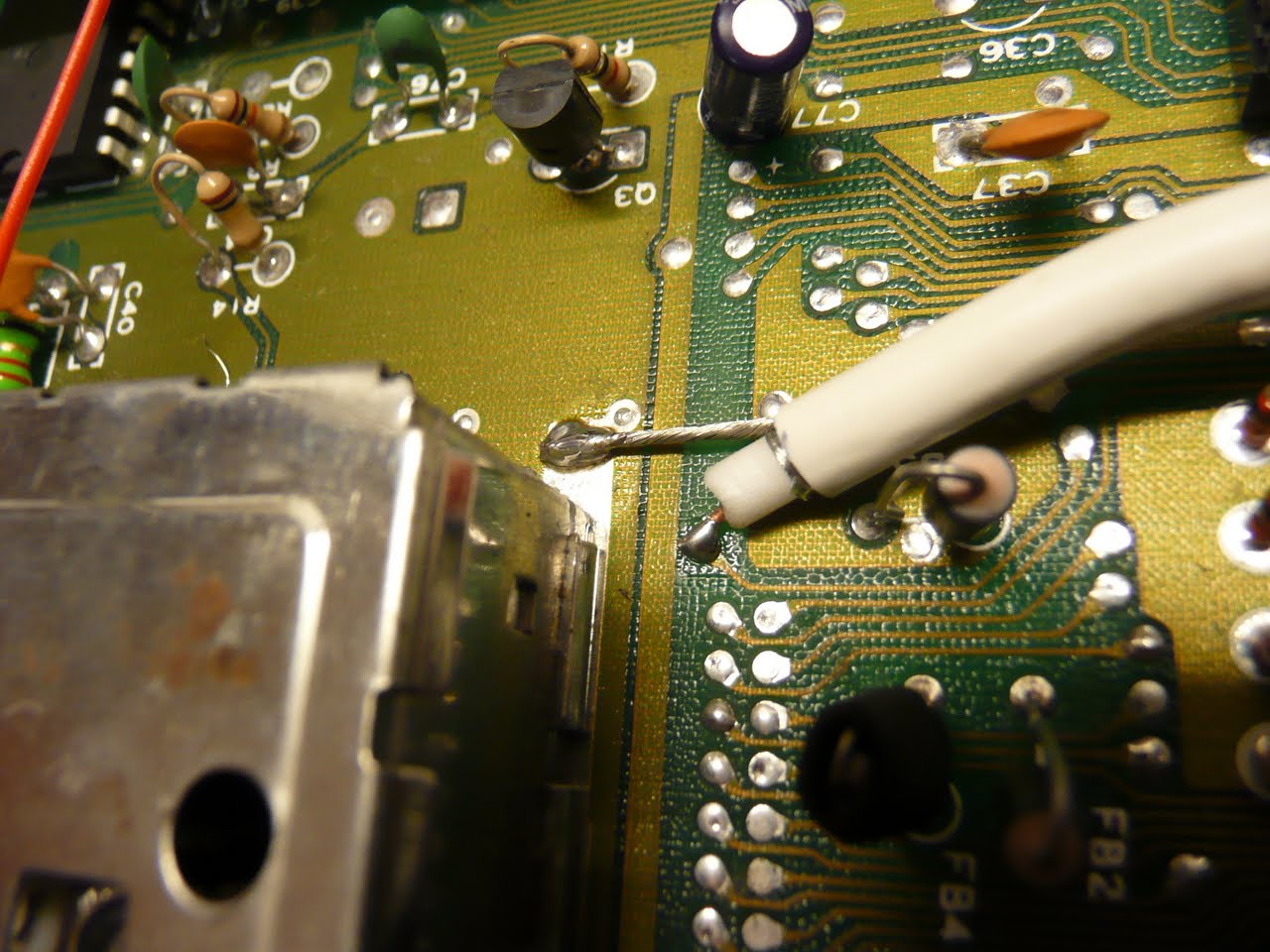
I found a post instructing to test the connectivity of certain solder points around and related to the transistor and doing this I found that there was a broken connection!
How was this possible! I'm an excellent solderer. I had come across people in the Mssiah forum with self admittedly poor soldering skills that had broken connections on the pcb or ruined it altogether but that kind of stuff doesn't happen to me. I got mad skilzzz!
I tested every connection on the pcb and found a second broken link. Looked at the spots with 10x magnification and could not see anything wrong whit one but the second one had a broken foil just at the edge of the solder point.. The only thing that could cause the foil to brake is when the solder cools and shrinks a little it pulls on the foil and tears it just at the edge of the soldering point. I had newer seen anything like this. I had seen similar and the cause is the same. The PCB is not intended for hand soldering but meant for factory solder baths or similar. 8bit ventures should make a new board with silk screening on the right side and made for hand soldering at home with cheap equipment= can stand excessive heating OR then have the components in place and no need for users to do any soldering. But for now the SID2SID board requires very low temperature solder and a soldering iron with a BELOW 300°C range. Most entry level cheap irons operate at +400°C and this will only ruin the SID2SID board. Kudos to 8bit ventures for the idea but double thumbs down for the execution. Please fix this the current SID2SID board is shit!
 Fixed connections.
Having gone over the entire board and tested every connection and replaced the transistor to a proper one I re run the diagnostics and FINALLY had sound from both chips.
SID2 was noticeably quieter and I had seen a post asking why is resistor R8 used for SID2 since commodores own schematics state that it is not to be used for 8085 chips. R8 will lower the volume. I checked my machine and SID1 did not have R8 so I removed it from SID2 and the levels were equal. this is another error in the instructions that are clearly written for a 6581 SID setup in mind. There is debate that some 8580 machines have R8 but my advice is use the same setup for both SID chips with or without R8 and similar transistors for both OR if your chips have a noticeable difference in volume use R8 to compensate.
 You can see that there is no R8 on the mobo.
Now that I had sound and the levels were equal I did a little test recording to examine the noise of the chips.
Both produce a lot of noise and as Big mech explains this is due to line in being open on the SID. This can be fixed by grounding ie. shorting the line in. BUT WAIT SID2 has no grounding at all! Why not 8bit ventures? During this project it has come clear that if you want equal sound out on the 2 SID's you have to have identical setup and conditions for both. including the grounding components for SID2 on the SID2SID board would have been easy. Now I have to do a dirty hack to fix that.


100k resistor and a 0,1uF capacitor are needed.


The lines are 50 Hz current hum comming from inside the C64. I'm not sure if there is anything to be done but they seem to originate inside the SID's.
SID2 still has more noise than SID1 witch might be caused by the capacitor that I'll change at some point.
I experimented with different grounding setups, just a wire, wire + resistor but they produced other errors in the sound so I'll live with the noise difference for now.
Now that the Mssiah was ready I needed some cables to go along with it for recording with my PC and hook up to stereo set when grooving.
Time for some robust Hi-Fi cables!


As this subject has been covered earlier I'm not going to get in too deep.
I made 2 RCA male cables and the pictured "recording cable" 2x RCA to stereo jack to hook up to my PC or other recording or sound gear.
The cables look really cool with the ridiculously expensive nylon sock on top.
Last but not least the pot box.
I decided to do the potentiometer controls from the start since turning knobs on synths etc. is cool and REALLY street credible ;)
I looked at things that others had done and tried to see if there was a good place for my pot's but any mounting on the C64 chassis would have involved nasty mutilation of the key board or the Honeywell 500kΩ medical grade pot's were too deep/long and would not fit depth wise. Also part of my design philosophy was not to chop up my 80's icon but leave it as original as possible. So a separate controller box was the way to go.

After a lot of researching I managed to find a reasonably priced box with the same angle/slope as the C64c has, only the plastic is not beige. I also wanted to stay with the 80's style so too modern or futuristic box and knobs would have looked tasteless.
First up was deciding upon an arrangement of the knobs and then drilling the face plate.
I wanted to maximize the finger room around the knobs so you can easel turn any combination or even have 2 people turn all at the same time.


As you can see the pots have a long treaded neck and to adjust for the depth one would need 2 nuts but these come with only 1 and I did not have anything like that so I made "depth adjustment washers" from 12mm copper tubing I had lying around.


The plastic knobs also needed a little grinding from under neath to get them to fit around the nut and turn without any difficulty.
The knobs are mounted as close as possible to the surface without touching the metal in any position.
The Mssiah instructions don't give usable wiring instructions and again I consulted the forum.
There I found wiring schemes. With ground wire and without ground wire.
I tested to see witch way to wire the pots since Honeywell's tech sheet does not tell you witch leg is + or -.
Then assembled the whole thing and gave it a test. The maximum value in Bassline was reached with something like half a turn.
The solution to this was to remove the ground wire and now there is 10-15% of excess left at the max end and I can live with that.
The picture shown still has the ground wire attached but the need for this depends on the pot's used.


Finally I added a little "high end feel" to the box by increasing it's weight with a hand full of nails and hot glue. Now when you pick the box up it feels like respectable hi-fi equipment and not like an empty soap box :) total weight being 592g. Oldest trick in the book. Just look inside your amplifier or cut open those store bought thick cables nothing but filler.
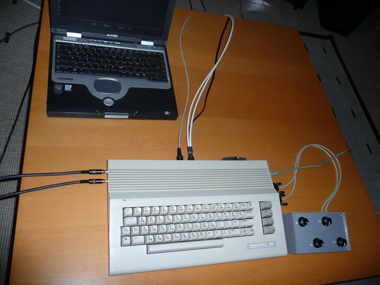
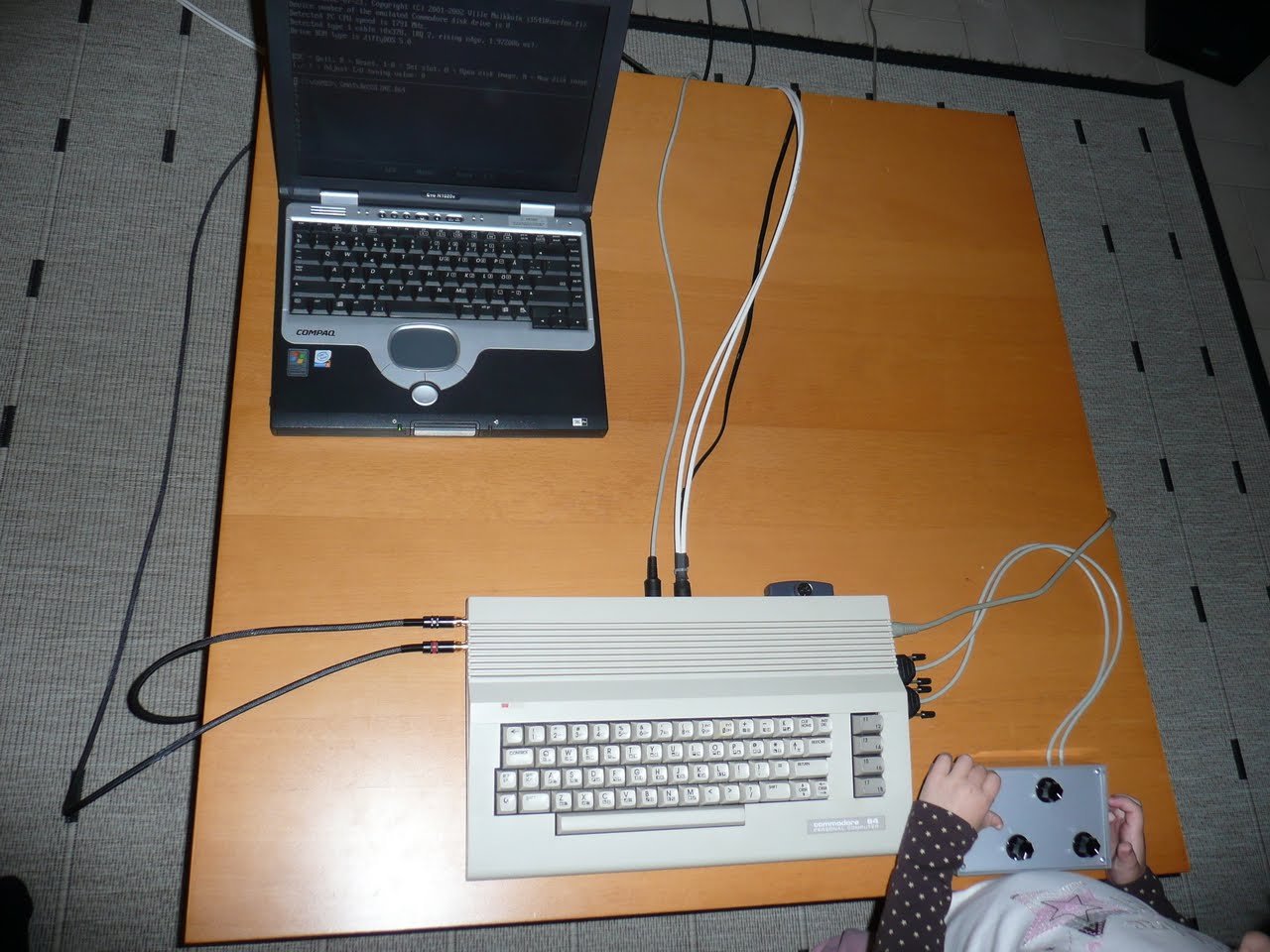
And last but not least 1541EMU+ Mssiah Bassline+ 2x Testi3 robust hifi cables+ old school pot box on it's maiden test. (the kid's like turning the knob's as well :)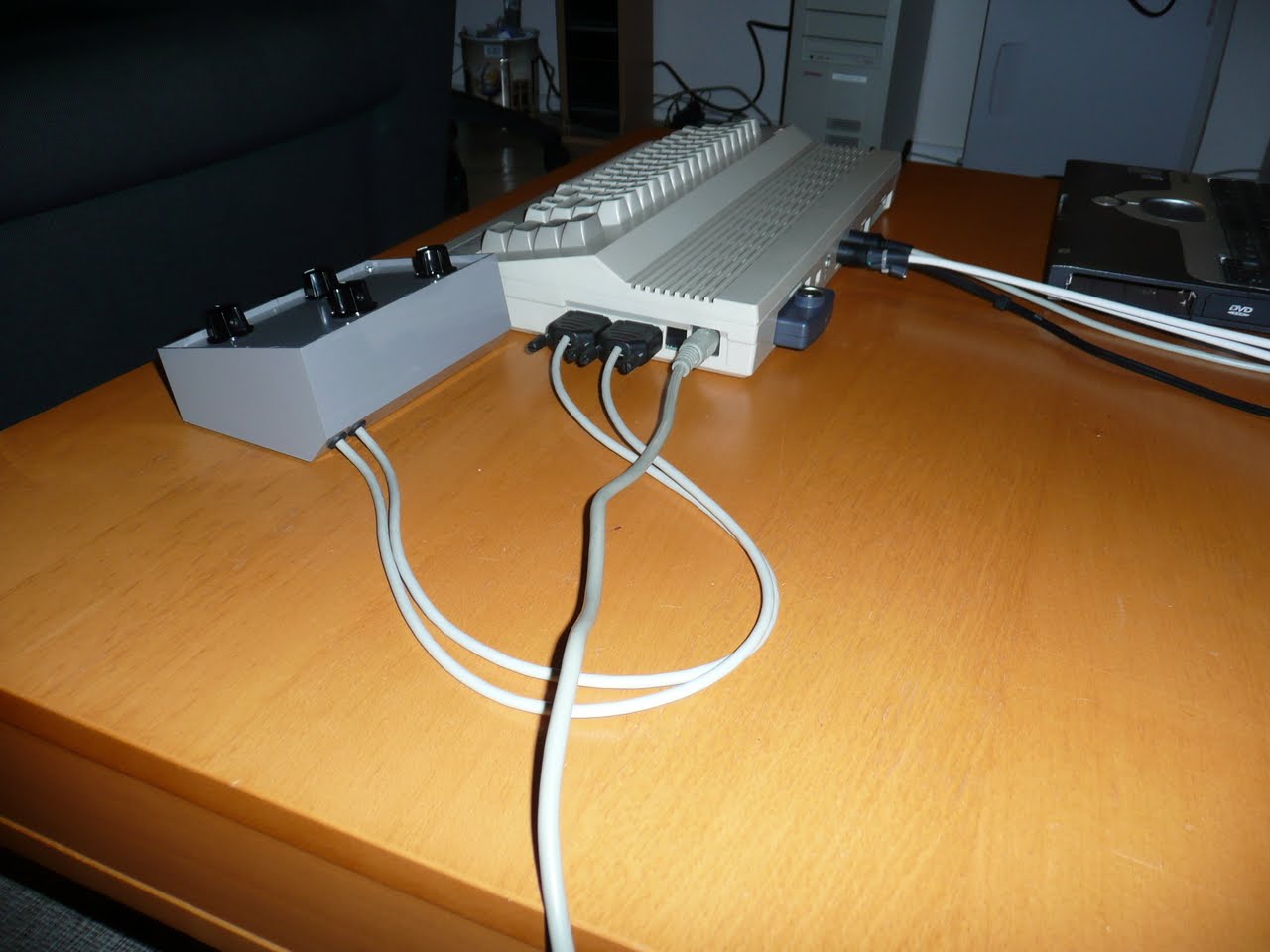


Long project but I'm happy with the end result. the pot box and live tweak-ability of the sound is really nice. Only thing I'm hoping for is a control surface/VST plug-in or similar so that Mssiah apps could be used from the PC.
Commodore 64 a modern stereo synthesizer.


4 comments:
Awesome article! Really inspires me to start getting into doing these mods.
Galand you found the article. It's a really nice and fun build to do. Just hope they have fixed that PCB. If your doing the "pot box" I recommend making longer cables.
Testi3
Thank you for your expert view on matters,
it helped me get sound on both SIDs.
Very practical and informative written and photographed.
Thanks.
Really glad I could help.
Post a Comment