Years ago I bought my first PVR/DVR what ever you like to call them the Topfield tf5100PVRt.
The only thing fundamentally wrong with the box was it's lack of a digital video out.
I did the research and it turned out that an SDI mod for taht box was impossible due to the fact that the mpeg2 decoder did not output a digital signal.
February 2007 I upgraded to TF5100 PVRt HDMI, a rare Topfield model that just hit the market in Finland and was pretty much the only box with a digital video out at the time.
The unit was said to be capable of outputting 480/576i over HDMI. That was exactly what I wanted, being a happy owner of a Lumagen video processor and all.

But as it turned out the "i" resolutions were promise ware and the feature was taken of the spec sheets and never implemented in firmware. In the US this could be class actionable.
I was convinced that an SDI modification was possible due to the design principle of using a separate digital output board just like in dvd players.


I also got confirmation from Topfield that the box uses the BT656 standard for the video transport to the Pioneer video processor chip (CD0041AF).
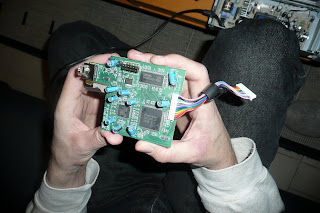
BT656 is the magic word here. It happens to be the standard for witch Moome makes his SDI mod kit and it's affordable unlike those over priced Pixel Magic kits.

The spec sheet for the Pioneer chip was easily found on the net and it's importance cannot be overstated. It tells you where you can find everything on the chip and all was left to us was to follow lines on the pcb and do a few measurements and the whole thing was as clear as day.

There are at least 4 different places you can get the BT656 signal from.
Pioneer processor legs, resistors before them, top or under side of the HDMI board side of the connector to the mother board or the motherboard side. The white connector on the HDMI board is not removable. You might even be able to substitute the hdmi board all together but figure out first what is that pin connection block all about.
Moomes instructions say 3.3V for the SDI board but the pcb has a 5V marking on it. Moome did confirm that this SDI board uses 5V, witch is what PixelMagic also use. 5V is easily obtainable from a number of places but we took it from the 5V connector of the power supply.
I decided to solder the SDI connector wires to the under side of the HDMI board. 8 wires for the 8bit BT656 data and 2 for the 27MHz clock signal and ground. The soldering was relatively simple but the ROHS solder used by Topfield did not want to melt at all so I soldered the wires on to the rohs solder. I know that the solder used in manufacturing is "harder" than what you would typically buy but I've never come across a solder that basically refused to melt and acted as solid metal!
We quickly assembled the unit for a test to see if the mod worked at all. After all there was a potential point of failure if the info from Topfiled about the BT signal used was incorrect this would be were we would find that out...
We were exited to see the litle led on the SDI board to light up and tell us it was getting the clock signal.
Little fiddling whit Lumagen's settings to configure the SDI input an BEHOLD we had video from the SDI output.
Quick look at the AVIA test patterns I had in the Toppy showed no errors and the picture quality looked to bee pretty good.
Looks like we got it right the first time. Me and my side kick Peki couldn't believe how easy this had been!
Now for the final assembly of the box and the little matter of making a hole for the SDI connector.
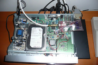
The Toppy is packed tightly enough to make the installation of the SDI card a bit hard. The only place i found where it could fit was under the HDD and it's a tight fit too. Replacing the HDMI board started to sound like a good idea but I always want to preserve the original workings of any equipment so I wasn't going to mutilate my precious hdmi output hole.
Making the hole itself was easy. I drilled a 3,5mm starting hole. Continued with a 10mm and then enlarged it with my age old Dremel to the 12+mm size required by the BNC connector.


The only problem we faced in the entire project was the fitting of the card. The HDD had to be moved as forward as possible and still the IDE cable did not fit through the space left in-between the SDI card and the HDD. We tried to change the IDE cable to a normal pc one but this was no go since the Toppy uses the prehistoric ide connection that has that 1 hole/pin no udma ide cables have. Yes we could have drilled the hole but if the pin has any functionality that would have been just stupid so we hand placed each wire in the ide cable so that it just fit in the gap. If the wires were overlapping each other it wouldn't fit or could cut one of the wires. Problem solved and time to "close the casket".


The unit worked flawlessly and now I had total control over the video. Quick testing showed that now it was possible to get rid off that annoying subtitle combing the Pioneer chip did. The colors were deeper and the picture sharper. Even some of the color bleeding seen in Topfield's own menus was gone. The only drawback was that the HDMI output no longer works properly. You get discolored video that wont sync. This could be due to the clock signal being robbed by the SDI card and the original signal strength is so weak that the Pioneer chip cant cope. I don't know if running a extra wire to the Pioneer clock would help or not this makes quality comparison impossible which I don't like so you just have to take my word for it.
The WOW factor of the SDI picture quality isn't that big but if you're a purist and have something to run that SDI output to (which probably means you ARE a purist) you'll enjoy the added picture quality and appreciate the amount of control you gain over video especially in situations where something needs to be done to correct interlacing problems etc. this mod is for you. Also if you just like to fiddle with electronics and have the skills, tools, couple of hours of time and a 100$ to spend this is a good mod to increase your street credibility ;)
Warranty seal intact!


